
REXXXX Series High Reliability Solid Rotor Brushless Resolvers (Store)
Size 08 (20mm) to Size 40 (100mm)
Resolvers are absolute, analog rotary encoders which are ideal for harsh environments. Unlike conventional optical or magnetic rotary encoder (with internal temperature-limiting electronics), the resolver is similar to a transformer in construction and does not incorporate any electronics. An external R/D (resolver-to-digital) interface is required which is also why the resolver can withstand extreme temperatures from cryogenic -196°C to extreme heat +200°C because there are no temperature limiting electronics in the resolvers themselves.
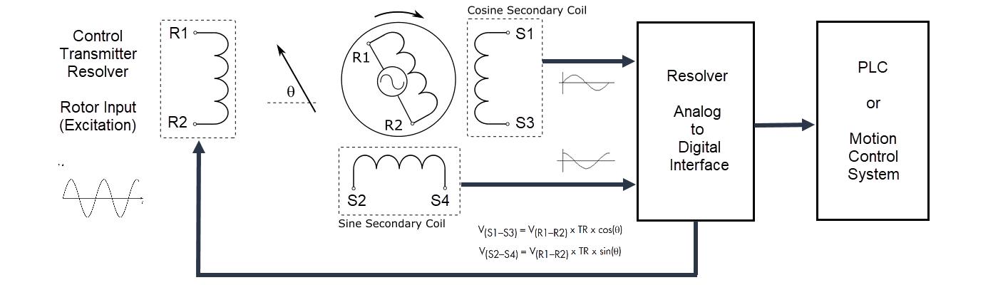
There are two types of resolvers: Control Transmitter and Control Transformer. The Control Transmitter features single excitation input to rotor input and sine/cosine stator outputs. The Control Transformer resolver requires both sine/cosine reference stator inputs and rotor output is a phase-shifted sine signal. For new designs, the control transmitter type resolver is recommended as commercial R/D interfaces are available from many manufacturers. For board level designs, R/D conversion ICs are available from Analog Devices and Texas Instruments.
Selecting a resolver is usually determined by shaft size, operating temperature, maximum rotational speed, air gap (shaft eccentricity), pole-pairs, and radiation resistace (if required).
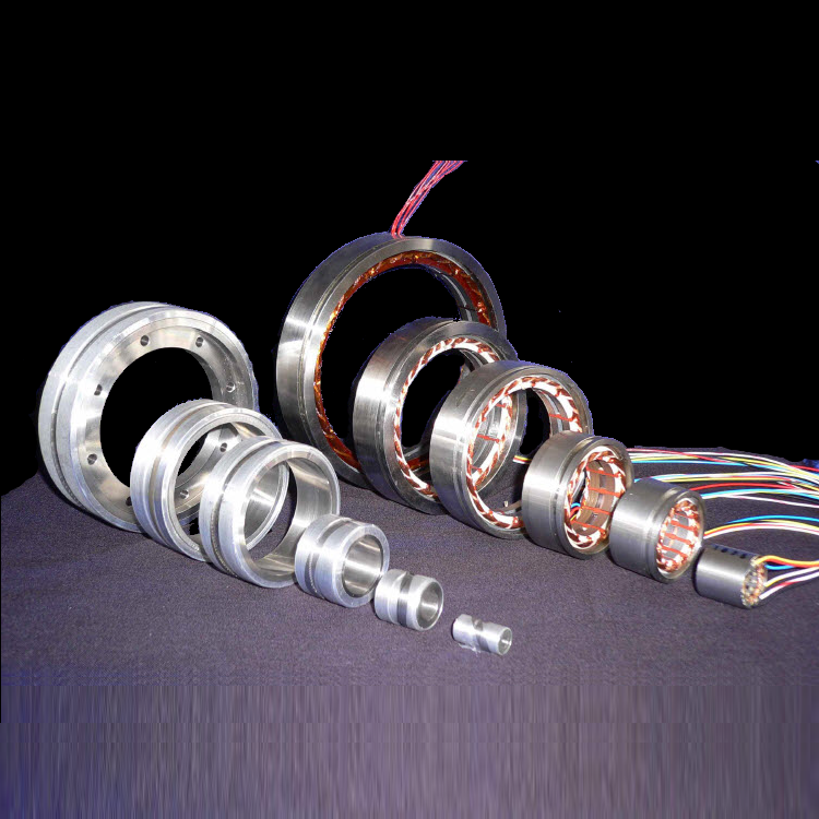
Microsyn RE2010 (size 08) / RE3620 (Size 15) / RE5032 (Size 21) / RE7557 (Size 30) are high performance, high reliability brushless, frameless resolvers ranging from Size 08 (∅0.8-inch or ∅20mm) to Size 30 (∅3.0-inch or 75mm).
Intermediate and Larger form factors, special shaft bores, lighter weight (titanium), and special mounting features are also available. Contact Micronor Sensors sales with your resolver requirements.
Product Details
| Reolver Type | REXXXX series are Control Transmitters (Rotor=Primary/Input, Stator= Sine/Cosine Outputs). |
| Electrical Speed (Pole Pairs) | Standard models are 1-speed (1 pole-pair), representing one sine/cosine output cycle per rotation. Multi-speed versions are available, depending on size. |
| Mechanical Speed (rpm) | Maximum rotational speed is determined by the size and mass of the resolver (see data sheet). For higher speed, lighter weight titanium bodies are possible. |
| Transformation Ratio (TR) | For Standard models, TR=0.5. Special TRs are possible. TR may be also determined by gap specification. |
| Accuracy |
Basic accuracy is 60 arcmin, assuming perfect alignment of rotor and stator. This is a limitation of the tolerances of the solid rotor design. For better accuracy, user should map angular position agaimst a high resolution encoder. |
| Shaft Mounting | If customer intends to press-fit shaft into rotor bore, then the shaft material should be chosen to closely match the temperature coefficient of the rotor base metal. Standard Speed rotors use aluminum while High Speed Rotors use Stainless Steel. |
| Stator/Rotor Air Gap |
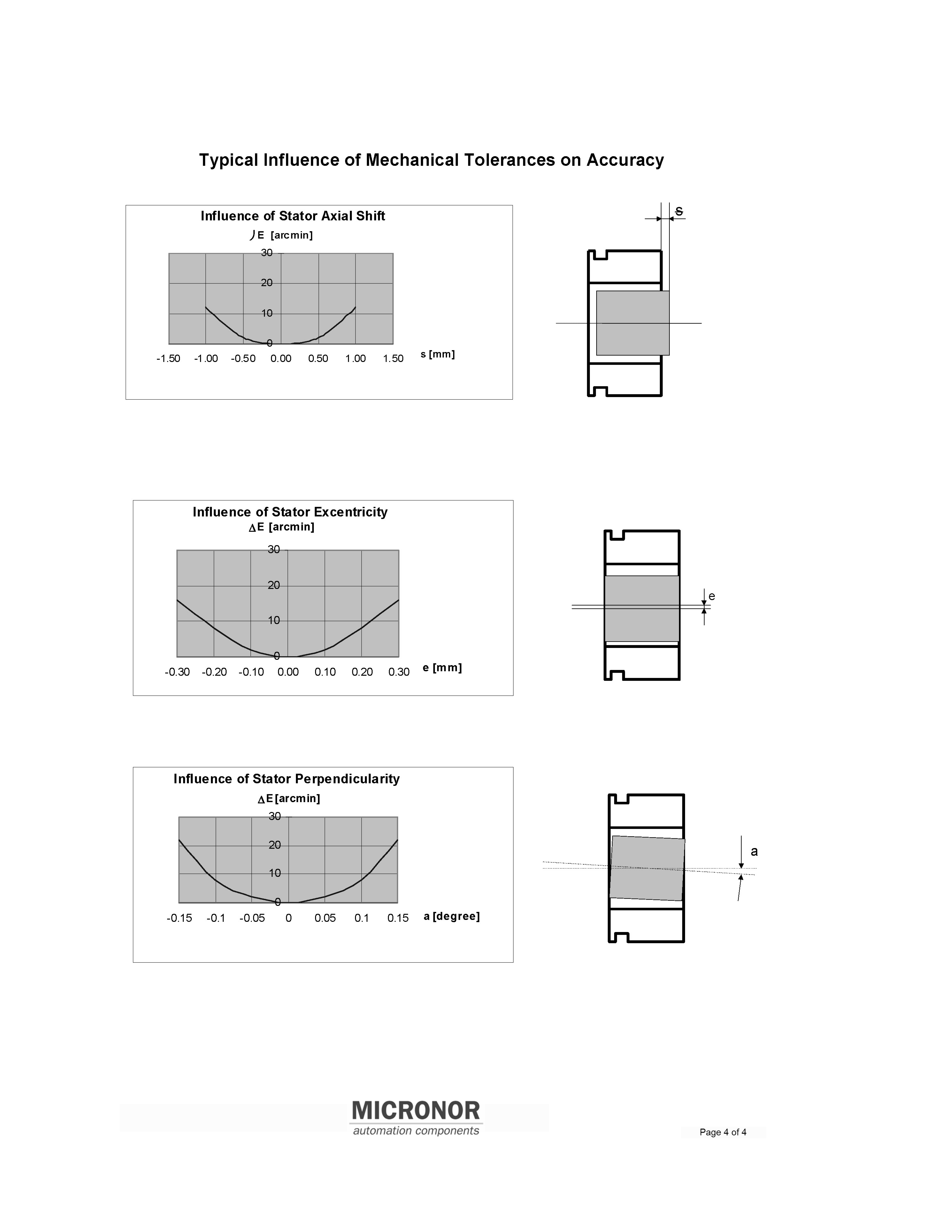
For Standard models, the gap between Rotor ID and Stator OD is 0.3mm. Linearity of output is based on mechanical alignment of rotor and stator (stator axial shift, eccentricity and perpendicularity). Larger gaps are possible, up to 1mm. For 1mm gap, the TR is reduced to 0.25. |
| Radiation Resistance | High temperature models are also radiation resistant. The estimated radiation resistance is 10 MGy in standard atmosphere and higher for vacuum or inert gas environment. This informationis based on data sheet values provided by the manufacturer of the componenets used in the resolver. |
| ORDERING CODE | REXXXX-Y-Z where XXXX=Size, 2010/3620/5032/7557 Y=Temperature, 1=Std Temp -40C to +135C, 2=High -70C to +200C, 3=Cryogenic -196C to +200C Z=Speed, 1=Standard (depends on Size), 2=High (depends on Size) NOTE: For pricing for High Speed models, contact Micronro Sensors sales. Currently, Cryogenic is only standard for RE2010 series. contact Micronor Sensors sales for other Sizes. |
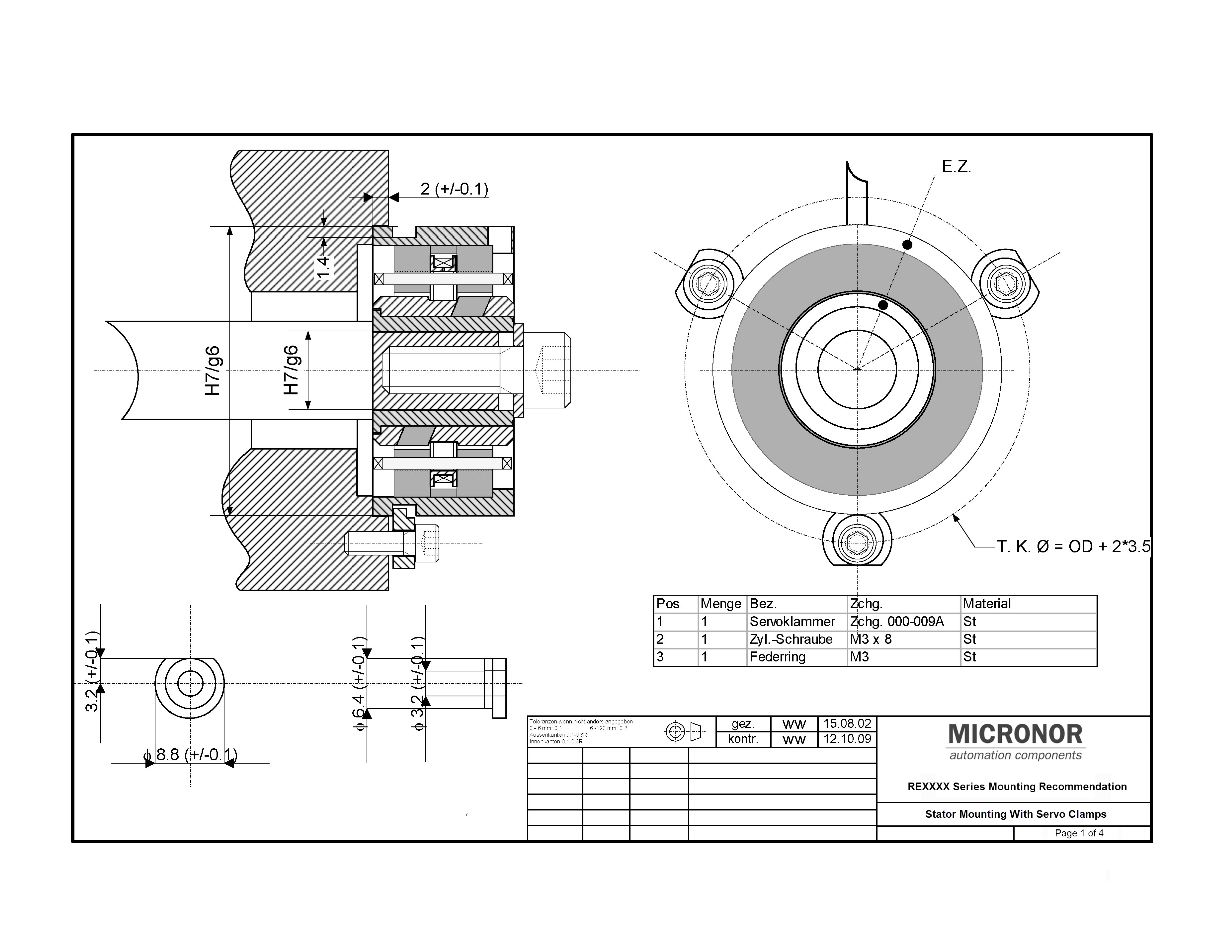
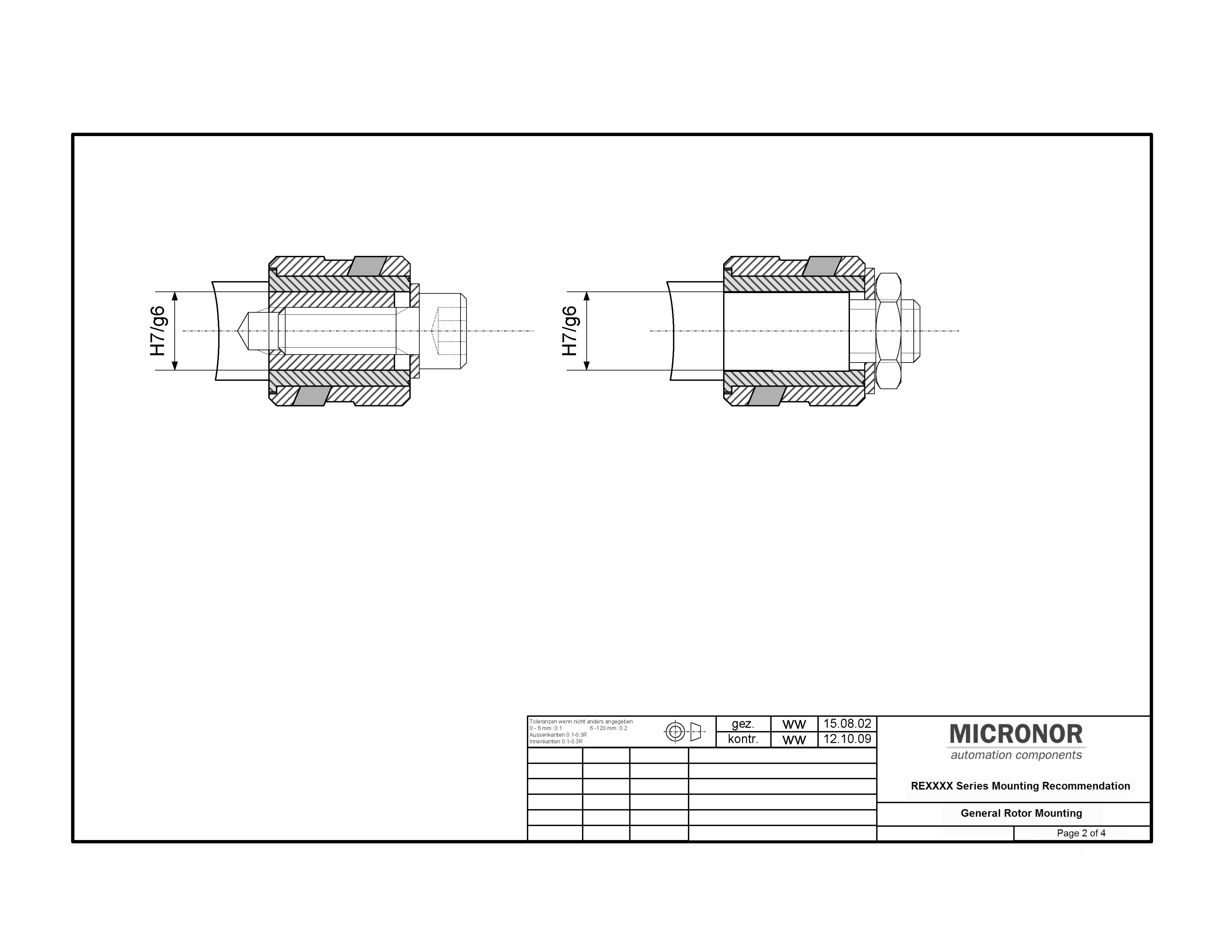
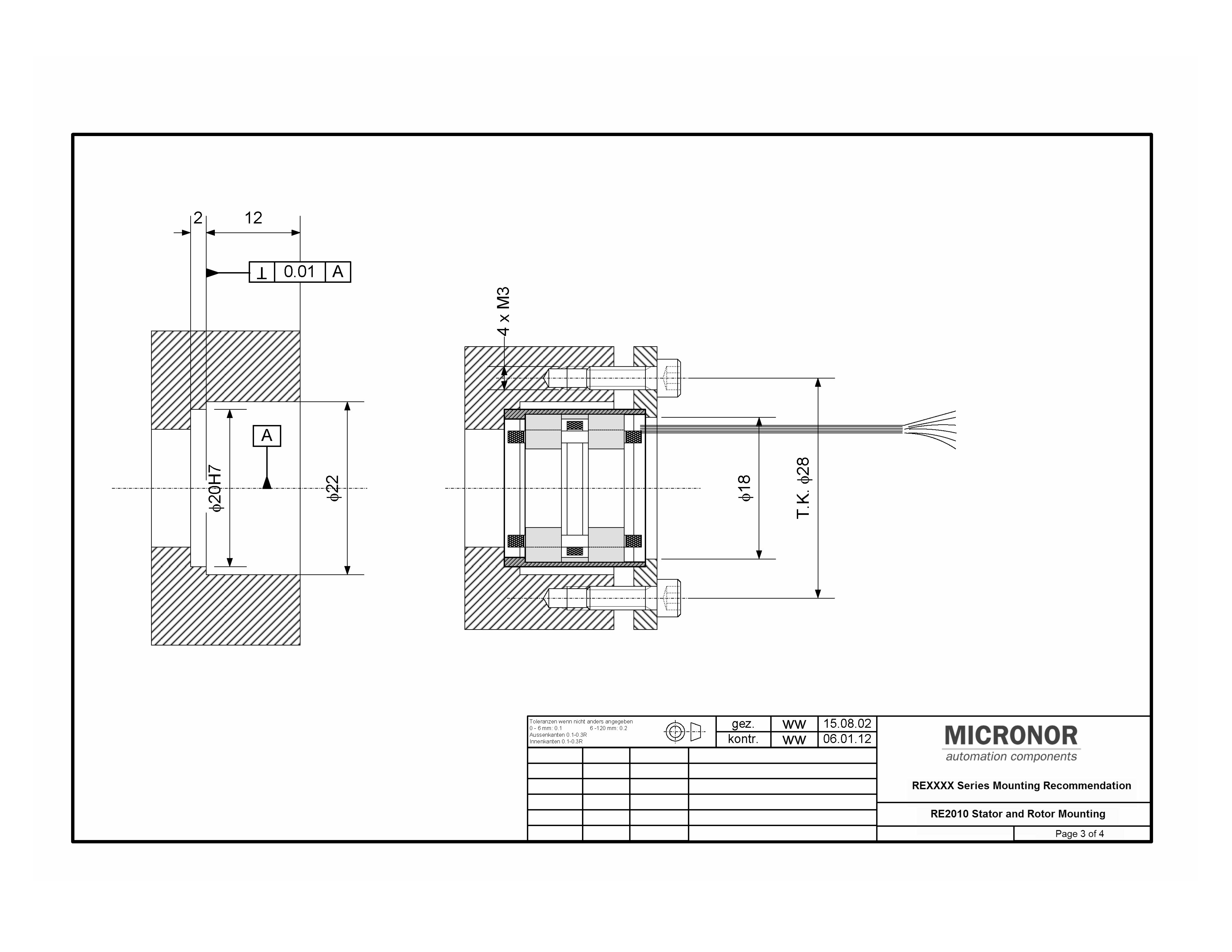
Resolver Mounting Guidelines
Resolver Interface Schematic
| Model | Description | Technical Docs | Availability | Unit Price | Quantity |
|---|